| Brief Description | |
|---|---|
|
File: \examples\Processing\Color\Bayer\BilinearBayer_RB_GG.va |
 |
|
Default Platform: mE5-MA-VCL |
|
|
Short Description The example shows the demosaicing of a Bayer RAW pattern of a bilinear line scan camera with color pattern Red/BlueFollowedBlue/Red_GreenFollowedGreen in "DeBayer Enhanced" and "DeBayer Fast" (is "Bayer Raw") mode. |
|
In the VisualApplets design example "BilinearBayer_RB_GG.va" the Bayer demosaicing for a bilinear line scan camera with colors red followed by blue or vice versa in the first sensor (top) line and colors green in the second (bottom) sensor line (or vice versa) is implemented. See Fig. 257 for the visualization of the sensor layout.
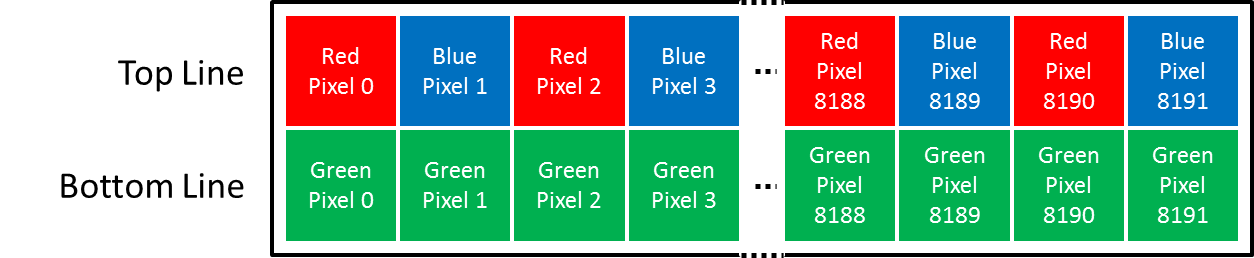
Figure 257. Sensor layout of a bilinear line scan camera with color pattern Red/BlueFollowedByBlue/Red_GreenFollowedByGreen
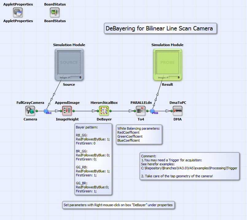
The Bayer demosaicing for this sensor layout is implemented in the applet for two camera modes: the "DeBayer Fast" mode and the "DeBayer Enhanced" mode. In the first case the motion between two acquisitions is two sensor lines, in the second case one line. Due to this, one color component is acquired for each pixel in the "DeBayer Fast" mode and two color components (red and green or blue and green) per pixel in the "DeBayer Enhanced" mode. In Fig. 258 you can see the basic structure of the design "BilinearBayer_RB_GG.va".

An image acquired in "DeBayer Fast" or "DeBayer Enhanced" mode by a bilinear line scan camera in Camera Link Full configuration (see camera interface operator FullGrayCamera) is demosaiced in the HierarchicalBox DeBayer. With "right-mouse-click" on this box you can choose the Bayer pattern and the white balancing coefficients for red, green and blue under "Properties". The fully color interpolated rgb image is transmitted to PC via DMA. The default platform for this design is microEnable 5 marathon VCL, but it can easily be adapted to another platform. For the design you can find test images for the "DeBayer Enhanced" mode and the "DeBayer Fast" mode under \examples\Processing\Color\Bayer\TestImagesBilinearBayer. The content of box DeBayer is shown in Fig. 259.
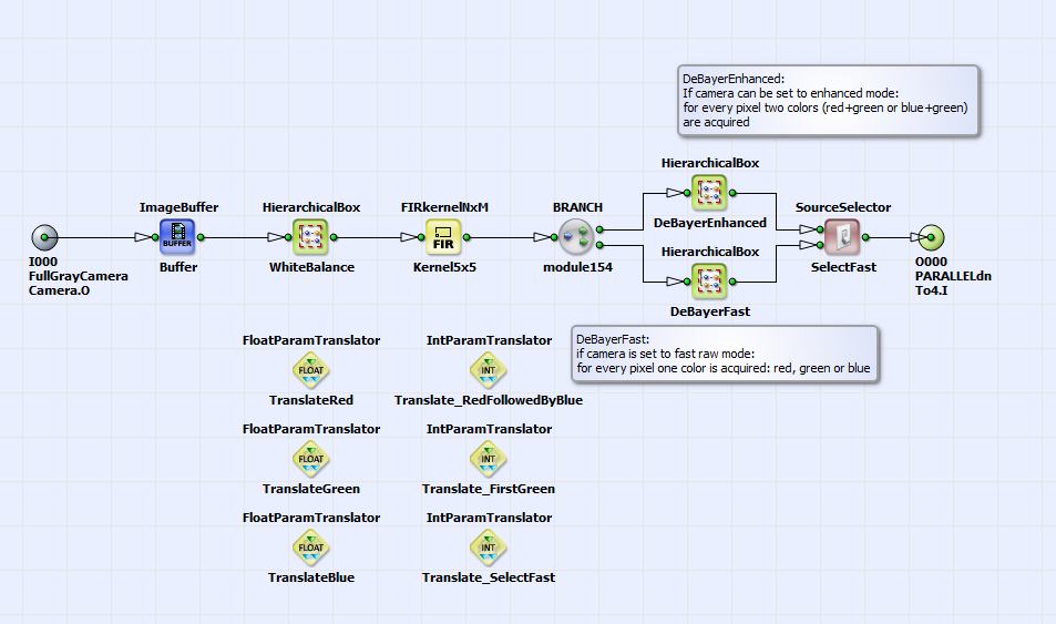
In the HierarchicalBox WhiteBalance a white balancing of the red, green and blue components is performed. You can choose the white balancing coefficients directly with "double-mouse-click" on the operator WhiteBalanceBayer in this box or with "right-mouse-click" on the box "DeBayer" as described above. The operator FIRkernelNxM_Kernel5x5 creates a 5x5 pixel kernel around the current pixel. With the operator SourceSelector_SelectFast you can choose the DeBayer mode DeBayerEnhanced or DeBayerFast. In Fig. 260 you can see the content of box DeBayerEnhanced.
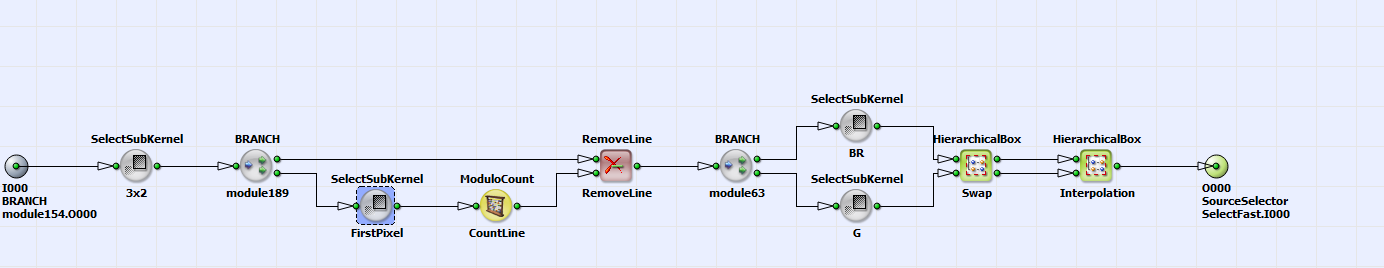
From the 5x5 kernel, a 3x2 sub kernel is selected. In the first row the red and blue values and in the second the green color values (or vice versa) are located. See for visualization of the kernel components order Fig. 261 for an example Bayer pattern of "RedFollowedByBlue_GreenFollowedByGreen".
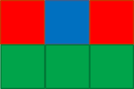
Figure 261. Kernel components selected in HierarchicalBox DeBayerEnhanced by operator SelectSubKernel3x2
With the operator combination SelectSubKernel-FirstPixel, ModuloCountLine and RemoveLine redundant image lines are removed. (The
line redundancy occurs from the kernel creation.) With the operators SelectSubKernel-BR and SelectSubKernel-G the red and blue kernel components are
separated from the green kernel components. If the Bayer pattern has the green values in the first kernel row, the components
can be swapped in the HierarchicalBox Swap with
the constant IsBRthenGG. The constant is set automatically, if you have chosen the Bayer pattern with "right-mouse-click" on the box "DeBayer" as
described above.
In the box Interpolation the missing third color component red
( ) or blue
(
) or blue
( ) at pixel position
 is interpolated according to:
where  are the green color components at pixel position
 .
The color components are finally merged together with the operator MergeComponents.
.
The color components are finally merged together with the operator MergeComponents.
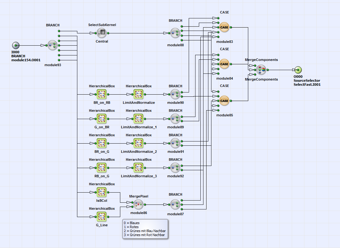
If you choose the "Bayer Raw" (also called "DeBayer Fast") mode of your camera, for each pixel only one color is acquired, due to the doubled line speed in comparison to the method described above. For this camera mode you can choose for DeBayering of the color components box DeBayerFast (see Fig. 259). You can see the content of box DeBayerFast in Fig. 262.
Here the DeBayering of the color components red  , blue
 or green
 at pixel position
  is performed in the following way.
The red or blue color components on a blue or red pixel are interpolated according to:
is performed in the following way.
The red or blue color components on a blue or red pixel are interpolated according to:

The green color components on a red or blue pixel are interpolated according to:

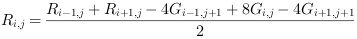
The red or blue color components on a green pixel in a red or blue pixel column can be calculated as:
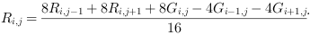
Finally the red or blue color components on green pixel in a blue or red pixel column are evaluated as:

For each pixel the evaluated red, green and blue color components are merged together with the operator MergeComponents (see Fig. 262) The complete image is finally transmitted via DMA to PC as shown in the basic design structure in Fig. 258.
